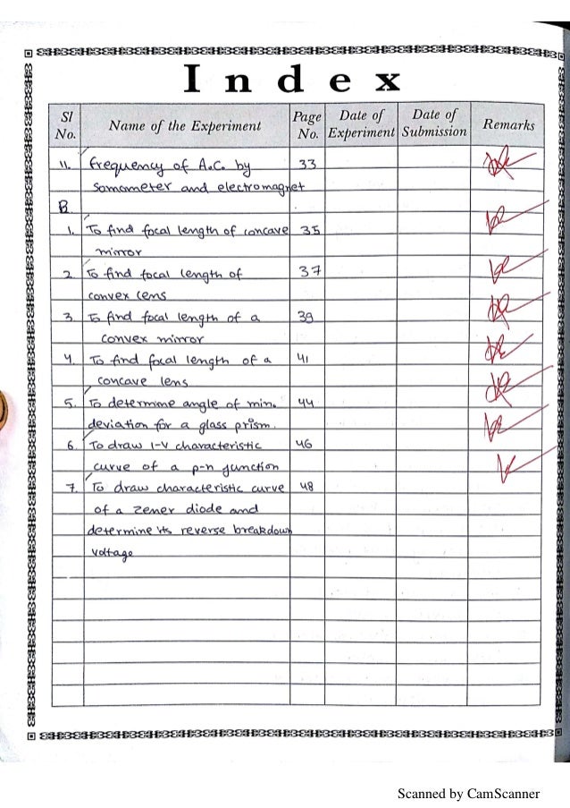
Class 12 Physics Practical File

EXP-1> TO DETERMINE THE RESISTANCE PER CM OF A GIVEN WIRE BY PLOTTING A GRAPH OF POTENTIAL DIFFERENCE VERSUS CURRENT Materials Required: A Resistance wire, voltmeter, ammeter, battery, rheostat, meter scale, one way key, connecting wires etc. Theory: If I be the current flowing through a conductor & V be the potential difference across its ends, then according to Ohm’s law V∝I or V = RI Where, R is the constant of proportionality. It is known as resistance of the conductor.
XII PHYSICS PRACTICAL MATERIAL (with sample reading & calculations) Q 1. Using the spectrometer, measure the angle of the given prism and angle of minimum deviation. Hence calculate the refractive index of the prism. Spectrometer I - Refractive index ‘ ’ of the prism. FORMULA: Refractive index of the material of the given prism. NCERT Class 9 Science Lab Manual Instructions. Download NCERT Chapters and Books in pdf format. Easy to print and read. Copies of these textbooks may be downloaded. CBSE Syllabus 2017-2018 for Class 12 Physical education has been released recently. It is available here for download in PDF format. CBSE Class 12 Physical Education.
V/I=R R depends upon the nature of material, temperature & dimensions of the conductor. Procedure: 1. Clean the ends of the connecting wires with the help of sand paper in order to remove any insulating coating on them. Connect various components - resistance, rheostat, battery, key, voltmeter and ammeter 3. Note whether pointers in milli-ammeter and voltmeter coincide with the zero mark on the measuring scale.
If it is not so, adjust the pointer to coincide with the zero mark by adjusting the screw provided near the base of the needle using a screw driver. Note the range and least count of the given voltmeter and milliammeter. Insert the key K and slide the rheostat contact to one of its extreme ends, so that current passing through the resistance wire is minimum. Note the milli-ammeter and voltmeter readings.
Remove the key K and allow the wire to cool, if heated. Again insert the key.
Shift the rheostat contact slightly to increase the applied voltage. Note the milli-ammeter and voltmeter reading. Repeat step 7 for four different settings of the rheostat.
Record your observations in a tabular form. OBSERVATIONS: 1. Range of ammeter = 0. Etp plant design software free download for pc. Least count of ammeter =.
Range of voltmeter = 0. Least count of voltmeter =.V 5. Least count of meter scale =. Length of the given wire, l =.m RESULT: 1.
The potential difference across the given wire varies linearly with the current. The resistance per unit length of the wire is (R ± ΔR) = (.
----------------------------------------------------------------------------------- EXP-2> TO DETERMINE RESISTANCE OF GALVANOMETER BY HALF DEFLECTION METHOD AND TO FIND ITS FIGURE OF MERIT. MATERIAL REQUIRED: A moving coil galvanometer, a battery or a battery eliminator (0 - 6 V), one resistance box (R-BOX 1) of range 0-10kΩ, one resistance box(R-BOX 2) of range 0-200 Ω, 2 one way keys, voltmeter, connecting wires and a piece of sand paper. Theory: Galvanometer is a sensitive device used to detect very low current. Its working is based on the principle that a coil placed in a uniform magnetic field experiences a torque when an electric current is set up in it.

The deflection of the coil is determined by a pointer attached to it, moving on the scale. When a coil carrying current I is placed in a radial magnetic field, the coil experiences a deflection θ which is related to I as I=k θ where k is a constant of proportionality and is termed as figure of merit of the galvanometer. Procedure: 1. Clean the connecting wires with sand paper and make neat and tight connections as per the circuit diagram 2. From the high resistance box (R-BOX 1) (1-10 kΩ), remove 5 kΩ key and then close the key K1. Adjust the resistance R from this resistance box to get full scale deflection on the galvanometer dial.
Record the values of resistance, R and deflection θ. Insert the key K2 and keep R fixed. Adjust the value of shunt resistance S to get the deflection in the galvanometer which is exactly half of θ. Torrent kursi specialist 1.
Remove plug K2 after noting down the value of shunt resistance, S. Take five sets of observations by repeating steps 2 and 3 so that θ is even number of divisions and record the observations for R, S, θ and 2 in tabular form. Calculate the galvanometer resistance G and figure of merit k of galvanometer using Equations. OBSERVATIONS: Emf of the battery E =.V Number of divisions on full scale of galvanometer =. Resistance of galvanometer by half deflection method, G =. Figure of merit of galvanometer, k =.ampere/division ----------------------------------------------------------------------------------- EXP-3> TO VERIFY LAWS OF COMBINATION OF RESISTOR USING A METER BRIDGE. Materials Required: Meter bridge, galvanometer, one way key, a resistance box, battery, jockey, two unknown resistance wires, and connecting wires.